"Realistic
2-Rail
Track and Switches for all brands of
S-trains"
 Track rail is weathered Solid
Nickel-Silver T-rail code 172 for stability and superior electrical
conductivity.
Track rail is weathered Solid
Nickel-Silver T-rail code 172 for stability and superior electrical
conductivity.
The rail does not corrode, oxidize or rust and is excellent for use in
all locations, from the very humid to the
very dry. Nickel-Silver is a copper-nickel alloy, considered to
be metalurgically similar to brass but superior
in
corrosion resistance. Brass oxidizes rapidly to a non-conducting
surface, which means that power will not
reach the
locomotives or cars, resulting in stalls. In general, Nickel
Silver is much better than brass, and is
worth the
small extra cost. The solid rail
absorbs sound better and makes for quiet train running. The
scale-
sized
plastic ties are molded
from UV resistant, high quality ABS plastic and have a realistic wood grain pattern, color, height,
width, length
and
spacing from real main lines that adds
to the
prototypical look of the track in a realistic fashion. The
weathered
rail
joiners have a detailed six bolt head design and come installed from
the factory
on all track and switches for proper electrical
conductivity. A snap
lock
system securely holds the track sections together to ensure exact
alignment and
good electrical contact.
When the track sections are
joined together
the tie
spacing remains uniform and this appearance is an exclusive design
found only
with
our track
system. The 60" flex track bends easily to an infinite variety of
curves. Switches
are closed frog allowing for operation
of all S gauge
wheel flanges. The track will accept original Gilbert track trips, mail
pick-up post, uncoupler, etc. The track has the
look of the real
thing, and the quality to back it up. Simply the Best track ever made
for the S-Gauge market.
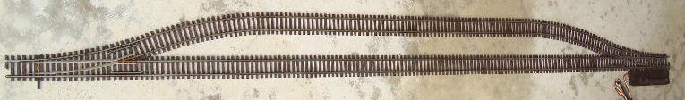
The
S-54 Remote Control Switches (27" radius, 54" centerline) come ready to
operate with illuminated green/red LED's on
push-button Remote Control Box with
five feet of four color rainbow wire wired
to switch machine. Target stand on switch
machine has illuminated green/red LED's for switch
position and two wires yellow/black for
transformer power supply hook up.

NOTE: The 27" radius
switch has a 1/3 curved removable track section at the end of the
curve that can be removed
making it suitable for use
with the 19"
radius curves, closer crossover track centers, sidings and yards.


The
27" radius
switch with the 1/3 curved attached makes a 27" radius curve.
Sidings take a 2/3, 27" radius curve and a 3" custom made straight
section of track to complete siding.


A
3" custom made straight section of track is needed to complete the
siding no matter how long.

Notice: Check Wheel Gauge
Improperly gauged wheels will
cause
arcing/shorting operating thru switches.
Wheel Gauge needs to
be checked
on running locomotives and cars for best operating results.
American “S” Gauge
track and switches are precision made to the
standards of the
(NMRA) National Model Railroad Association and (NASG) National
Association S-Gauge.
The A.C. Gilbert
Co.made many size metal wheels that were never gauged
correctly on
cars and engines from the factory. All METAL
WHEELS that draw curent made by
A.C. Gilbert Co. and
LTI AF must be properly gauged to prevent arcing/shorting on switches.
With calipers wheels should be gauged .725 thousandths
between the inside of the wheels.
An easy test is to place a
dime between the wheel sets, spreading
them carefully as necessary.
This is necessary since
wheel gauge changes
on older equipment with use and some were never
set correctly to begin
with. Be
careful not to spread much further than
the dime
spacing since that
can be a problem as well.
This makes for a quick
gauge
and once done will yield a better running train. Some wheels
will
drift on their axle's very easily. If you have any of them, clean the
axle and wheel of any grease,
then apply a small amount of glue on the
axle and slide the wheel over the glue when gauging.
That way the wheel
set will stay in gauge and not cause a problem in later use.
Switch
Motor Information:
American "S" Gauge
switches are equipped with a "twin coil" switch motor
(also known as
a "snap switch"). This consists of two electric coil motors that
draw
between 3-5 amps to snap
the switch into a straight or turn position upon
activation so an
adequate amount
of current from a proper supply voltage is required.
The recommended
operating
voltage is 16 to 18 volts AC with a minimum of 40va.
Failure to provide for
this amount of power can destroy the switch machine's motor
by requiring you to
activate for a longer time than normal. This type of switch motor,
with
adequate power, will operate the switch in a split second. Otherwise,
more time
is required which may possibly overheat the switch motor. This is why
activation has
to be momentary. Momentary activation is accomplished by
depressing the momentary
control box switch button for not more than a second. The
switches
throw very rapidly
when powered with the proper size power transformer.
Excessively
long activations will overheat the switch motor and cause total
destruction
which is not covered under any warranty. Failure to
use
adequate wiring and sufficient
power to operate the switch is not a reflection
to the quality of the switch.
These
switches are "Non-Power Routing" which allows for constant current to
be
supplied
to both tracks.

Control Box
Information:
The
remote switch control
box can be connected to any AC power
transformer
providing 16 to 18 volts AC with a minimum of 40va with the two
feet of black-
yellow power input wire supplied. For older transformers, connect
the black wire
to the base or "U" transformer post and the yellow wire to the 15 or 18
volt fixed
voltage post. Newer Transformers may be labeled
differently. With this hook-up
the remote switch
control box and switch target stand are illuminated at all times
indicating the
proper switch
position. When
stacking multiple remote switch control
boxes use the metal
jumpers (included) for a continous power input.
One control box per switch motor is
the design. If more than one switch operation is desired,
you will have to purchase and mount separate momentary push buttons
capable of handling
the current necessary for the switch coils.
Parallel switches cannot be operated with one control box
as it will overload the control box making it stick and burn up the
switch motor voiding warranty
SPST
(single pole single throw)
switch on switch sidings to turn power ON and OFF
To isolate a switch siding track
section that can be independently operated
for on/off operation use
item
#2601, brown plastic insulating rail joiners, one on same side of rails
past each switch end
with item
#2701 power feed rail joiner, one only required and any SPST switch with a minimum
3 amp switch capacity to turn power on and off.

Crossover with 3.25" track
centers. 1/3 track section removed.

Crossover with 7.25" track centers. 1/3 track
section attached.

Siding with 3.25" track centers. A 2/3, 27" track
section attached.

Switch yard with 3.50" track centers. 1/3 track
section removed.


We have had inquiries
asking about the apperance of the switch
ties when the switch
motor is removed. Removal of switch motor leaves all
ties intact.
Switch
Motor Mounted

Switch
Motor Removed with all ties intact


November
19, 2006. Temporary
6' x 18' layout with Articulated
Steam Engine running
smoothly through S-54 switches at the Cal-Stewart, TTOS, Toy Train
Operating Society
meet in Pasadena,
CA.


"Realistic 2-Rail
Track" for Tinplate, Hi-Rail, and Scale
10" Straight, 19", 27"
Curve, and
60"
Flex in Stock
"Realistic 2-Rail Track" designed to look like US Prototype.
Both the Flex and Sectional Track come weathered with
weathered N/S
Rail Joiners installed.
American "S"
Gauge™ Track Features:
- Operates all S-Gauge Tinplate, Hi-Rail,
and Scale
- Compatible with Original Flyer track
- Can attach Flyer Accessory Trips and Uncoupler
- Solid code .172 Nickel/Silver rail weathered
- Rail is 65% Brass with 12% Nickel/Silver
- Excellent electrical pickup, with no oxidation or rust
- Flex track bends easily without kinking
- No templates, bend fixtures or special tools required
- Ties molded from high quality ABS, UV resistant plastic
- Realistic wood grain tie pattern
- Six bolt-head N/S rail joiner, weathered
- Track snap-locks together
19" & 27" Starter Kits in Stock!
- 19” Radius Track Starter Kit –
 Order Form
Same radius as original American Flyer® track.
- 27” Radius Track Starter Kit – Order Form
Email: nmescher@classictrains.com
Promoting "S" The ideal size to operate, handle, and enjoy.

© Copyright 1980-2018 Classic Trains.
All rights reserved. No portion of this website may be copied
without prior written permission of Classic Trains
All prices subject to change without prior notice.